
User guide
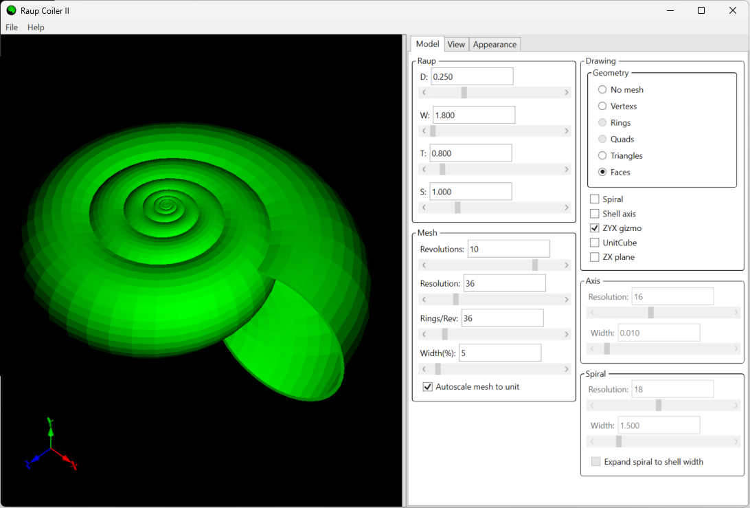
The application interface has three areas: on the top, the main menu, on the left, the 3D viewport and on the right, the tab pages panel:
3D viewport.
Top main menu bar.
Tab pages panel: with the following tab pages:.
- Model tab page.
- View tab page.
- Appearance tab page.
3D viewport.
Top main menu bar.
Tab pages panel: with the following tab pages:.
- Model tab page.
- View tab page.
- Appearance tab page.
Any change you make in the parameters of the right panel appears in the viewport immediately. Every numeric parameter has a text box and a scroll bar to set its value. For most parameters, a value you type outside the allowed range is clamped to the nearest limit.
3D viewport
The 3D viewport is where the 3D shell model and other geoemtry is rendered. The most important actions that can be done in the 3D viewport are:
- Left-drag: rrbit the camera by keeping pressed the left button and move the mouse. Horizontal movement changes ? (azimuth) and vertical movement changes ? (zenith).
- Mouse wheel: zoom in or out by changing the camera distance ?.
- Double-click: hide or show the parameter panel, so the viewport can use the whole window.
- Narrow bar between viewport and panel hide or show the parameter panel.
Top menu bar
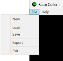
These are the menus available in the top main menu bar:
File menu:
- New: Resets every parameter to its default value. You are asked to confirm first, because the current shell is discarded.
- Load: Opens a `.rii` file and restores all the parameters saved in it: model, mesh, view, light and colours.
- Save: Saves all current parameters to a `.rii` file. This is a plain JSON text file, so you can read or edit it by hand.
- Export: Writes the current shell mesh to a 3D file. Choose the format with the file extension: `.stl` for 3D printing or `.obj` for other 3D tools. Vertices are scaled by 40 on export. Only the shell is exported, not the axis, spiral or other helper objects.
- Exit: Closes the application after asking for confirmation. Closing the window has the same effect.
Help menu:
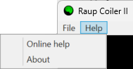
- Online help: online documentation of this software.
- About: shows the product name, version, build date and license link. It also shows an the intro page with software news and the links to the project website and download page to get the latest version.
Tab pages panel
The tab pages panel contains different tab pages with different panels each one. Each panel groups different parameters that allow to configure the shell 3d model geometry and appearance. The available tab pages are:
• Model tab page
• View tab page
• Appearance tab page
• Model tab page
• View tab page
• Appearance tab page
Model tab page
The model tab page contains different panels which group the parameters used to define the shell geometry and to configure the helper objects drawn in the viewport.These are the panels and the options available in the model tab page:
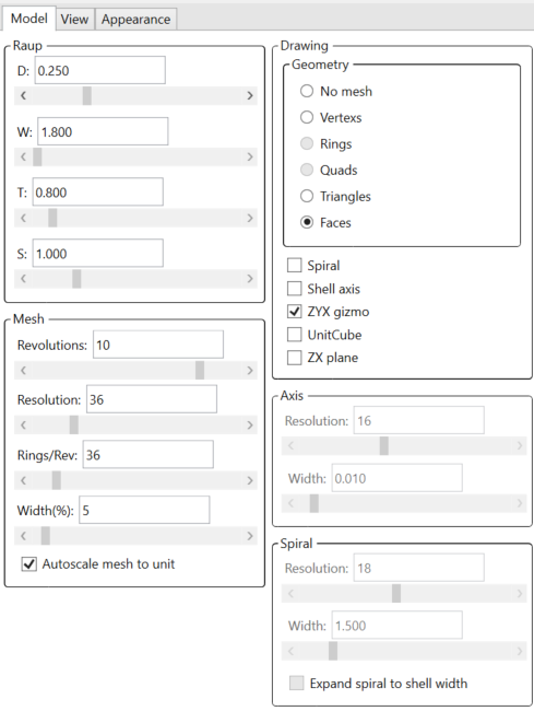
Raup panel: the four parameters of the coiling model, 'D', 'W', 'T' and 'S'. See [The Raup model](#the-raup-model) for what each one does.
Mesh panel: controls how finely the shell surface is built.
- Revolutions: number of full turns of the shell around the coiling axis.
- Resolution: number of vertices in each ring, the cross-section of the tube.
- Rings/Rev: number of rings generated for each revolution.
- Width(%): thickness of the shell wall, as a percentage of the tube radius. The shell has both an outer and an inner surface.
- Autoscale mesh to unit: scales and centres the shell so it fits within the ?1.+1 cube, keeping it in view for any parameter values.
Drawing panel: chooses what the viewport draws.
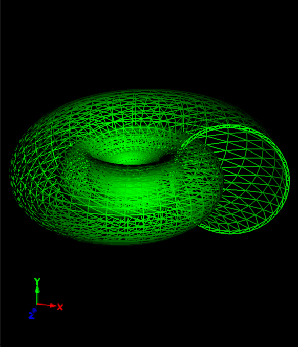
- Geometry: How the shell is rendered: **No mesh** (shell hidden), **Vertexs** (points only), **Triangles** (wireframe) or **Faces** (shaded solid surface). *Rings* and *Quads* are shown but not available yet.
- Spiral: Shows a tube that follows the coiling path of the shell.
- Shell axis: Shows the coiling axis as a cylinder.
- ZYX gizmo: Shows the X, Y and Z axes at the origin, to help with orientation.
- UnitCube: Shows the ?1.+1 cube. When autoscale is on, the shell fits inside it.
- ZX plane: Shows the horizontal ZX plane. It makes the effect of the T parameter (translation along the axis) easier to see.
Axis panel: (available when *Shell axis* is checked):
- Resolution: Number of sides of the axis cylinder. | 3 - 36 |
- Width: Radius of the axis cylinder. | 0.001 - 0.2 |
Spiral panel: (available when *Spiral* is checked):
- Resolution: Number of sides of the spiral tube cross-section.
- Width: Thickness of the spiral tube.
- Expand: spiral to shell width** | Makes the spiral follow the full shell cross-section instead of using a thin tube. When this is checked, *Width* is disabled.
View tab page
Contains the option to configure the camera and the light.These are the panels and the options available in the view tab page:
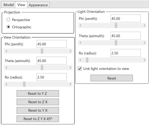
Projection panel:
- Perspective: sets perspective projection. Objects further away look smaller, as in a realistic view.
- Ortographic: sets ortographic projection. There is no perspective distortion. This is useful for comparing proportions. It is the default.
View Orientation panel: positions the camera with spherical coordinates. The camera always looks at the origin:
The preset buttons in the View Orientation panel move the camera to standard views without changing the distance:
- Phi (zenith): Vertical angle of the camera, in degrees.
- Theta (azimuth): Horizontal angle of the camera around the vertical axis, in degrees.
- Ro (radius): Distance from the camera to the origin.
The preset buttons in the View Orientation panel move the camera to standard views without changing the distance:
- Reset to Y Z: 0°, 0°
- Reset to Z X: 90°, 0°
- Reset to Y X: 0°, 90°
- Reset to Z Y X 45º:45°, 45° (isometric-like view; this is the default).
Light Orientation panel: with the options to position the light source with the same spherical coordinates (?, ?, ?). The ? range for the light is 0 - 50:
- Link light orientation to view: when this is checked, the light's angles follow the camera, so the side of the shell you are looking at is always lit. It is on by default.
- Reset: puts the light back at ? = 0°, ? = 0°, ? = 4.
Appearance tab page
With different options to configure the colors and transparency of the 3D model:
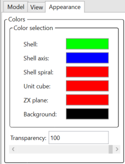
Colors selection panel: click any colour button to open the colour picker and change the colour of that element. The elements are the Shell, Shell axis, Shell spiral, Unit cube, ZX plane and Background.
Transparency: sets the opacity of the shell from 1 to 100. At 100 (the default) the shell is fully opaque. Lower values make it more see-through, which helps you look at the inner whorls, the axis and the spiral. The setting applies only to the shell.
Transparency: sets the opacity of the shell from 1 to 100. At 100 (the default) the shell is fully opaque. Lower values make it more see-through, which helps you look at the inner whorls, the axis and the spiral. The setting applies only to the shell.

